Types Of Logic Gates Circuit Diagram Electrical Schematic Symbol Logic Gates CAD Block And Typical Drawing Logic Gates The Building Blocks Of Digital Systems Logic Gates Types Working Principle Application Advantage Computer Science All Logic Gates Introduction How Gates Works The Logic Gates Animation Instrumentation Tools Logic gates are circuits that implement the logical AND OR NOT and other boolean functions whose truth tables we studied last week There are many ways to implement logic gates using transistors but the most common is known as comple mentary metal oxide semiconductor or CMOS which uses pMOS and nMOS transistors in a complemen
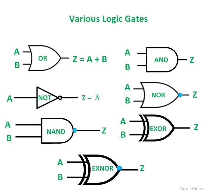
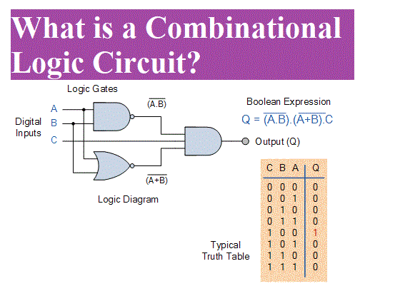
Google Classroom Computers often chain logic gates together by taking the output from one gate and using it as the input to another gate We call that a logic circuit Circuits enables computers to do more complex operations than they could accomplish with just a single gate The smallest circuit is a chain of 2 logic gates Consider this circuit The three types of logic gates are represented by standard symbols as shown in Figure 1 3 Since the inputs and outputs of logic gates are just wires carrying on off signals logic gates can be wired together by connecting outputs from some gates to inputs of other gates The result is a logic circuit An example is also shown in Figure 1 3
Logic Gates Animation Instrumentation Tools Boolean Expression For Logic Gates Logic Gates Symbols Arduino And Fun Pinterest Charts Gates And Basic Logic Gates 7 Steps Instructables Logic Gates Types Working Principle Application Advantage What Are Logic Gates Various Types Circuit Globe 3 Input Logic Gates Truth Tables Pdf Review Home Decor Equivalent Circuit Using Logic Gates Circuit Diagram COMPUTER SCIENCE Logic Gates And Types Of Logic Gate Of Computer
Types Of Logic Gates Circuit Diagram
 Types Of Logic Gates Circuit Diagram
https://i1.wp.com/www.linecad.com/wp-content/uploads/2017/04/Electrical-Schematic-Symbol-Logic-Gates.png
Logic gate diagrams would look like this OR gate An OR gate has two inputs OR tells us that EITHER Input A OR Input B has to be 1 or ON in order for the output to be 1 Otherwise the
Pre-crafted templates offer a time-saving option for creating a varied range of documents and files. These pre-designed formats and layouts can be utilized for various individual and expert jobs, consisting of resumes, invitations, flyers, newsletters, reports, presentations, and more, improving the material production procedure.
Types Of Logic Gates Circuit Diagram

Electrical Symbols Logic Gate Diagram

Boolean Expression For Logic Gates

Logic Gates Symbols Arduino And Fun Pinterest Charts Gates And

Basic Logic Gates 7 Steps Instructables

What Are Logic Gates Various Types Circuit Globe

3 Input Logic Gates Truth Tables Pdf Review Home Decor

What is Logic Gate A digital electronic circuit that is made to perform certain logical operations is defined as Logic Gate It can be designed using any Non Linear Device The sole condition is that it must consist of two different regions for operation

Logic gate A logic circuit diagram for a 4 bit carry lookahead binary adder design using only the AND OR and XOR logic gates CMOS diagram of a NOT gate also known as an inverter MOSFETs are the most common way to make logic gates

There are three basic logic gates OR gate AND gate NOT gate Each logic gate is indicated by a logical symbol and its function is described either by a Truth table or by a Boolean expression Truth Table of Logic Gates A logic gate may have one or more inputs but only one output

1 0 B 0 AND is a Boolean operation an operation that takes values that are either true or false and then outputs true or false based on a logical manipulation of those inputs In logic gates we consider 1 to be true and 0 to be false

Gates and Logic From Transistorsto Logic Gates and Logic Circuits Prof Anne Bracy CS 3410 Computer Science Cornell University The slides are the product of many rounds of teaching CS 3410 by Professors Weatherspoon Bala Bracy and Sirer Goals for Today From Switches to Logic Gates to Logic Circuits Transistors Logic Gates Truth Tables
Logic gates are the basic building block of digital circuits Basically all logic gates have one output and two inputs Some logic gates like NOT gate or Inverter has only one input and one output The inputs of the logic gates are designed to receive only binary data only low 0 or high 1 by receiving the voltage input View all books Learning Objectives In this post you will practise drawing logic gates diagrams using the following logic gates AND Gate OR Gate XOR Gate NOT Gate First you will need to learn the shapes symbols used to draw the four main logic gates Symbol Logic Gate Logic Gate Diagrams Your Task Use our logic gates diagram tool
Logic Gates Logic gates are the building blocks of a digital circuit Every terminal in a logic gate will always be in one of the two binary states 0 or 1 These binary states represent the presence 1 or absence 0 of an electrical voltage Binary 1 can be referred to as positive or ON whilst binary 0 can be called negative or